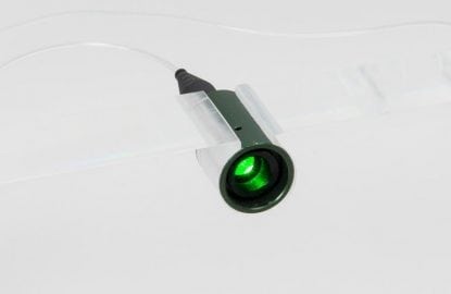
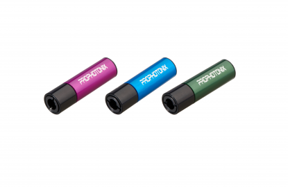
A digitally controlled laser offers functionality advantageous for your application versus an analog laser module. This post details the benefits of using a digital laser module including control and monitoring functionality as well as highlighting the ease of using a digital interface
There are various methods to operating a laser module; from simple application of power (on/off) to achieve the required output, to utilizing a digital interface to operate and observe laser operation.
The choice you make for the laser module depends on the application in which it is being used, and what level of control and monitoring you require. Cost is also a consideration.
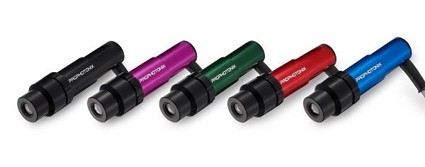
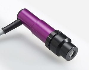 If your application requires enhanced control and monitoring functionality, then utilizing a digital interface is essential. The PROdigii laser module does this for you, offering control and monitoring of multiple aspects via an interface that is easily incorporated into your overall system.
Why Would You Want to Control and Monitor Via a Digital Interface?
Typically, systems requiring the use of a laser module component will also incorporate other elements communicating via a digital interface. Having a common interface through which a single control system can operate these modules is a distinct advantage, keeping the design as concise as possible.
Should a failure occur in the laser module, a fast diagnosis of the problem is essential to ensure a timely repair can be performed to get the system running. Data from the laser module will alert the user/operator, in the graphical user interface, of the failure mode [see the PROdigii Digital Interface image below] allowing a fast resolution. In addition, data from the laser module confirms its operation is within your specified limits and indicates when preventative maintenance activities should be scheduled rather than relying on reactive repair.
In comparison, achieving an enhanced set of operational information via non-digital interface is simply not practical.
Digital Laser Module Features
PROdigii incorporates an industry standard RS485 serial interface offering control functionality as well as a series of fault indications and analog operational values that can be used for monitoring purposes.
The digital laser can be configured to operate in a wide variety of operational modes in a range of optical configurations. Some items of available information are specific to certain configurations of operation.
Operational information is available on a polled basis. Commands can be pushed as required.
Also available is information about the laser module itself: Part and serial number, revision, and build date, etc, all of which allows quick identification of the component within your system.
Control commands include:
| Control | Description |
| On | To transition the module into the Optical output on state. |
| Off | To transition the module into the Ready state. |
| Output power control | To set the required optical output power. |
| Operation mode (ACC) | To set the module to operate in the constant current (ACC) mode. |
| Operation mode (APC) | To set the module to operate in the constant power (APC) mode. |
| Set user defined identification | To set the user defined identification within the laser module. |
Fault and operational information include:
| Control | Description |
| Laser diode current | Returns the current laser diode current |
| Photo diode current | Returns the current photo diode current |
| Laser diode temperature | Returns the current laser diode temperature |
| General module temperature | Returns the current general module temperature |
| Input voltage | Returns the current input voltage |
| Laser diode supply voltage | Returns the current laser diode supply voltage |
| Optical output power – Average | Returns the current optical output power – Average |
| Optical output power – Peak | Returns the current optical output power – Peak |
| Modulation duty | Returns the current modulation duty |
| Modulation frequency | Returns the current modulation frequency |
| Modulation pulse length | Returns the current modulation pulse length |
| Hours count | Returns the current hours count |
| Laser diode slope efficiency | Returns the current laser diode slope efficiency |
| Output energy count | Returns the current output energy count |
What is Involved in Using a Digital Interface?
Simple really – First establish a connection between your chosen controller and the laser module. This can take the form of a simple USB to RS485 . Our engineers can recommend a suitable type.
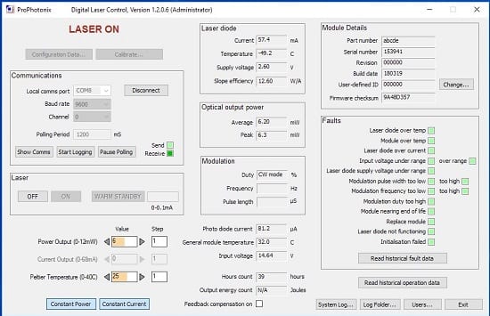
After establishing the necessary connection interface, ProPhotonix offers an initial start-up Laser Control application that can be quickly used to start operating the module within your system. If more than one laser is being used, each can be individually addressed.
The Laser Control software gives the user full access to the available functionality. Commands sent between our Laser Control software and the laser module are available for integration into your own bespoke software as part of your overall system.
What does the PROdigii Digital Laser Module offer?
Aside from the many optical configurations available in the PROdigii digital laser, the common digital interface allows flexibility for the laser module to be optimized for your application. The laser module features a configuration file setup on installation and can be configured to your specific application.
Configuration allows laser operation to be maintained within safe operating regions to ensure long laser life. It also sets the levels at which the various fault indications will occur. All this information is internally stored in non-volatile memory.
ProPhotonix has specialists to advise on the operation of the digital laser interface and how to best utilize the available information. For more information, contact us at sales@prophotonix.com
